8877 "Lite"
A 50 MHz (6m) 20lb Travel Amp
by
Dick Hanson, K5AND
April 2005
 As those of you who do expeditions and mountain-top contesting can attest,
carrying a kilowatt amp on your quest is SO much fun. Over the years since 1987,
I have created 5 travel amps, all for six meters. The first was a highly
modified Tokyo Hy-Power HLK-1A, followed by a Yaesu FL-2100, followed by a
single 3CX800 (for W6JKV), followed by a pair of 3CX800s, followed by a single
8877 with separate power supply, followed by a single 3CX800 with built-in HV
supply with a smaller (lighter) HV transformer.
As those of you who do expeditions and mountain-top contesting can attest,
carrying a kilowatt amp on your quest is SO much fun. Over the years since 1987,
I have created 5 travel amps, all for six meters. The first was a highly
modified Tokyo Hy-Power HLK-1A, followed by a Yaesu FL-2100, followed by a
single 3CX800 (for W6JKV), followed by a pair of 3CX800s, followed by a single
8877 with separate power supply, followed by a single 3CX800 with built-in HV
supply with a smaller (lighter) HV transformer.
These amps all had one thing in common..�they were a real challenge to
transport. The last one was the best of the lot with respect to "footprint" and
weight, but still weighed in at 30 lbs, minus blower, plus 12 lbs for the
luggage bag for a total weight of 42 lbs. I wanted a carry-on package that would
weigh less than 30 lbs and available wall voltage notwithstanding, an amp that
would deliver 1500 watts under normal conditions.
Time for an extreme makeover?
It�s pretty hard to "shrink" a conventional HV power supply, even with
careful sizing of the transformer, smaller filter caps etc., but it is the power
supply that offers the most potential for shedding pounds.
Ever since seeing a prototype regulated HV switching supply in the Command
Technologies booth at Dayton several years ago, I�ve dreamt about "imbedding" a
HV switcher in an amp. Watts Unlimited was the first commercial entry into the
HV switching arena, so after months of studying the product and asking questions
of its creator, I decided to try one.
Most "new" technologies have pros and cons, so you must evaluate both.
The "pro" side of the Watts Unlimited PS-2500A is:
- Lightweight (10 lbs)
- Reasonable voltage regulation from idle to full-load (5-10%)
- Electrically "quiet", although this does not matter much here since the
supply is only "on" during transmit.
- Capable of supplying enough power for 1.5KW RF output
5. Instead of providing a fixed bias in the
cathode (assuming triode tubes) and then changing the bias from cut-off to
operate with a cathode relay shorting out a 25K ohm 10 watt resistor, in this
amp, there is no cathode relay. Since there is no relay to switch from cut-off
to operating bias, the tube will draw idle current as soon as the PTT circuit
is activated. This eliminates at least several components from the amp.
"Cons" to keep in mind include:
1. The supply cannot be turned on without a load. To do so would be to
guarantee a failure of the output caps, as the resulting HV would soar over
their 4KV rating. The manufacturer recommends a minimum idle current of 150-250
ma at turn-on. So if you�re going to use a Zener for the operating bias, you
pre-select a Zener that will make the tube draw 150 ma or so at idle.
- Another thing to consider is that the supply does not come "on" when you
turn on the AC power switch. It requires an external nominal 5-12VDC source to
switch it on. The user needs to provide a DC on-off source voltage activated
by the PTT circuitry. While this is not an obstacle, you need to be aware of
this requirement in your planning.
Design criteria for this amp
Let me say now that this is more of a "concept" article than a complete nuts
and bolts, step-by-step how to article. That said, if you have built an amp
before, you should feel right at home with this material.
Because of my requirement for 1.5 KW RF output, and because of the regulation
characteristics of the power supply, it seemed that a single 8877 would be the
easiest tube to implement. Other tube(s) considered were my personal favorites�.the
3CX800. But for this application, the single 8877 worked best with the power
supply idle current requirement.
With the 8877 idling at 150 ma the instant the supply is switched on, the
anode voltage is 3400 volts. At full load of 850 ma, the anode voltage drops to
3 KV. The power supply remains cool and electrically quiet while "dormant" even
though 240VAC is present. When the PTT is activated, the supply goes from 0
volts to full output in a few milliseconds.
Other features of this amp are:
- Relatively small box (less blower): 6.5"H by 13.5"W by 12"D
- Weight: 20 lbs, including built-in power supply
- No protrusions from the cabinet (to break in transit)
- no knobs; screwdriver adjust for plate and load caps
- AC line entrance with flush plug and socket
- plate and grid meters are protected behind front panel
4. 3 minute time delay to hold off PTT until cathode warms up
5. Built-in RF input/output relay switching
6. Vacuum plate cap and physically small meters to help "shrink" cabinet
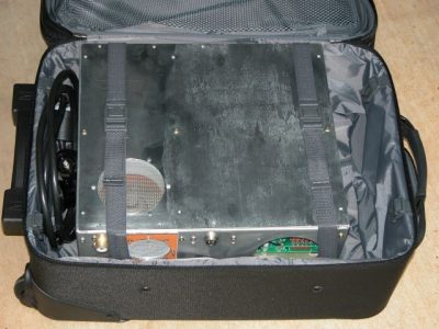
7. Must fit inside a rolling carry-on Travel Pro bag (wt. 8 lbs); these
bags are made of Teflon-coated ballistic Nylon and are lightweight, durable,
strong and water-resistant; best of all, they have really great wheels and
an extendable handle!
- Should be capable of "high duty modes" (like JT65) for EME work (an extra
exhaust fan over the tube).
- There is no grid protection in this amp. Since I will be the primary user
of the amp, I felt that the additional circuitry required (and the space that
it would require) was not justified. So the operator is responsible for not
applying way too much drive, and, for not applying any drive in the absence of
anode voltage. The 3 minute time delay to hold off the PTT until the cathode
is "warmed up" is the only "protection" built into this amp.
- This amp will not win any beauty contests, but it will be durable.
Building the amp
For me, the hardest part of a project is planning the metal work which of course
is dictated here not only by the size of the components, but also by the airline
size limitations for �carry-on baggage�. Charlie Byers of Byers Chassis supplied
the chassis and its �innards�. I had some more metal work done by a local
machine shop, and I used imbedded captive nuts for cabinet assembly rather than
gambling on my fat fingers trying to get a nut on a screw.
Since this is a single band (in fact, almost single frequency) amp, it does not
require much tuning. So if you can eliminate the protruding tuning knobs�..why
not? I made a couple of knobs with �� shafts and then milled the ends of the
shaft �stubs� to resemble a flat screwdriver blade. These assemblies are
temporarily inserted into the plate and load panel bushings on the front panel
so that you can in fact tune with a knob in �set and forget� fashion. The
cathode tuning capacitor is also a screwdriver adjustment, and once set, will
hold tuning over at least 1 MHz.
This amp uses a conventional Pi circuit instead of my normal Pi-L circuit in
order to save a little more space. I always carry a high-power ICE six meter
filter, so no worries about 2nd harmonic rejection. The blocking cap is an �857�
type, rated at 15KV and a �lot� of current.
The RF input/output relay board is same one I have been using for a number of
years now. The SPDT Schrack relays have very robust contacts, and the amp
off-line VSWR may be �tuned out� using the little thru-line capacitor to ground
trick mentioned in an earlier article.
The 3 minute time delay for cathode warm-up is provided by a common Omron
H3YN-2, 0-10 minute delay relay; the delay is set for 3 minutes, an eternity
when the band is open and the amp is warming up...
The power cord set is a heavy duty IEC arrangement featuring a standard 3-prong
male chassis mount connector mated to a 3-wire, number 12 AWG power cord about
8� long. The plug end is left un-terminated so that you can put on whichever
male plug may be required for the country you�re visiting. Again, this
�connector� approach on the amp was used to eliminate �protrusions� which can be
damaged in shipment. The AC mains are turned on and off by a recessed DPST
switch rated at 10A at 250VAC. The filament and control voltage �combo�
transformer is an Ameritron unit; PN 406-1419-3J; $49.95.
Specifications
No surprises here.
With 40-50 watts of drive, the amp will put out 1500 watts with 2500 watts
input.
The anode voltage is about 3000 volts under a load of 850 ma. Grid current
runs between 40-60 ma with this loading and anode voltage.
If you have an MFJ 259, you can do all your preliminary tuning before
applying high voltage. Getting the cathode and tank circuits "in the ballpark"
before applying drive is always a good feeling.
Installation of PS-2500A supply
The good news is�.very few connections are required for this unit. The
sobering news is�.mistakes are either costly, dangerous or both. Fortunately,
the manufacturer has done a very nice job with documentation; the manuals are
excellent. I would suggest taking extra time reading and understanding the
manual regarding the following points:
- AC connections, including neutral
- B minus
- HV turn on-off
- B plus connection
- Metering
- Jumpering
The supply factory default wiring means 240VAC mains; it also means the B
minus connection is tied to chassis ground. Most linear supplies have the B
minus "floated" above ground several hundred ohms for metering purposes, which
is the option I chose; this means you need to remove the B minus jumper to
ground. The negative terminal of the plate meter is connected to B minus; then
this point goes to chassis ground thru a 200 ohm 10 watt resistor in parallel
with a 6 amp 1KV diode. This affords both current measuring as well as
protection for meters and PS components.
I likewise chose to turn the supply "on & off" with +12VDC supplied thru the
PTT circuit.
Schematics and instructions for the power supply are not furnished here but
are available for download from the manufacturer.
In closing, remember: Failures on a mountaintop or in some foreign country
are easier to prevent than to repair�. (ancient Ham proverb)
If anyone has any questions on this project, please phone or e-mail.
One postscript is that it would be possible to shrink the cabinet one more
inch in height. If you eliminate the 1" tall fan mounted below the PS heat sink
and change the air flow (and vents!) from front to back, you could wind up with
a cabinet only 5.5" high! You pretty much need all of the 13.5" of width and all
of the 12" of front-to-back depth though.
Dick Hanson, K5AND
7540 Williamsberg Dr.
Cumming, GA 30041
Tel:
+1 770-844-7002
email: [email protected]
The PS-2500A may be obtained from:
Watts Unlimited (Tim Hulick)
886 Brandon Lane
Schwenksville, PA 19473-2102
Tel:
+1 610-764-9514
email:
www.wattsunlimited.com
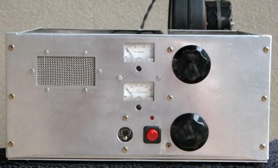
Front view,
showing exhaust port on left, plate current meter top center.
Also
showing the grid current meter at center, recessed power switch and amp in/out switch
with LED indicator above. Top removable knob upper right is plate tune; lower
removable knob is plate loading. Air intake for power supply is on bottom of
cabinet. RF compartment is pressurized so that 95% of air exhausts thru anode
cooler and the rest exits thru the cathode compartment.
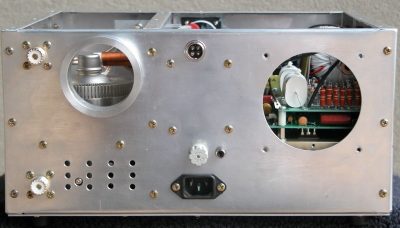
Rear view, showing RF input and output connectors at bottom left and top
left.
Also showing the mounting flange for blower, cathode compartment air exhaust (under blower
flange, AC power connector for blower and fan upper center, fuse, RCA PTT, and
AC mains connector, hole for muffin fan at far right. Both openings are
"screened" with stainless screening.
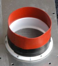
Teflon chimney with rubber "extension" for pressurizing anode compartment
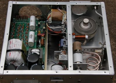
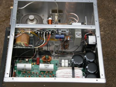
Top view, showing Watts Unlimited PS-2500A switching power supply at far
left.
The center section is the control circuitry, including filament transformer,
time delay relay and metering. The RF compartment is on the far right.
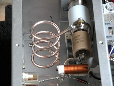
Larger view of tank circuit.
Showing silver-plated
tank coil, 3-30 vacuum variable, 857 blocking cap, RF plate choke and almost
buried at the bottom, the 200 pf loading cap.
Another view of RF deck, showing
the 8877.
Also showing the anode clamp and input/output relay
switching board, featuring the Schrack relays. Also note the Teflon RG-142 coax
for the output. Will handle the 1.5 KW without meltdown! Also shown is part of
the control circuitry: Omron time delay relay and Tripplett 120G series plate
and grid meters. The fuse at the center is the 1 amp cathode circuit fuse.
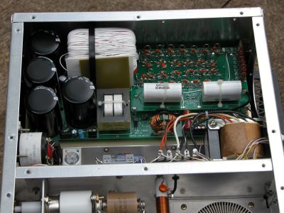
This shot shows the PS-2500A high voltage switching power supply.
The white
thing at top left is the high voltage transformer; the 50 ohm, 50 watt glitch
resistor* is upper right. The two HV output caps are center right; total output
"C" is 0.2 mf at 4000 VDC.
*Note: the glitch resistor is not really necessary with this supply since it
features an automatic shut-down circuit which activates if the supply tries to
draw more than 19 amps.
Still, old habits die slowly for me; can�t hurt to have the extra protection
of the glitch.
Schematics
Power Wiring