The Amplifier RF Deck
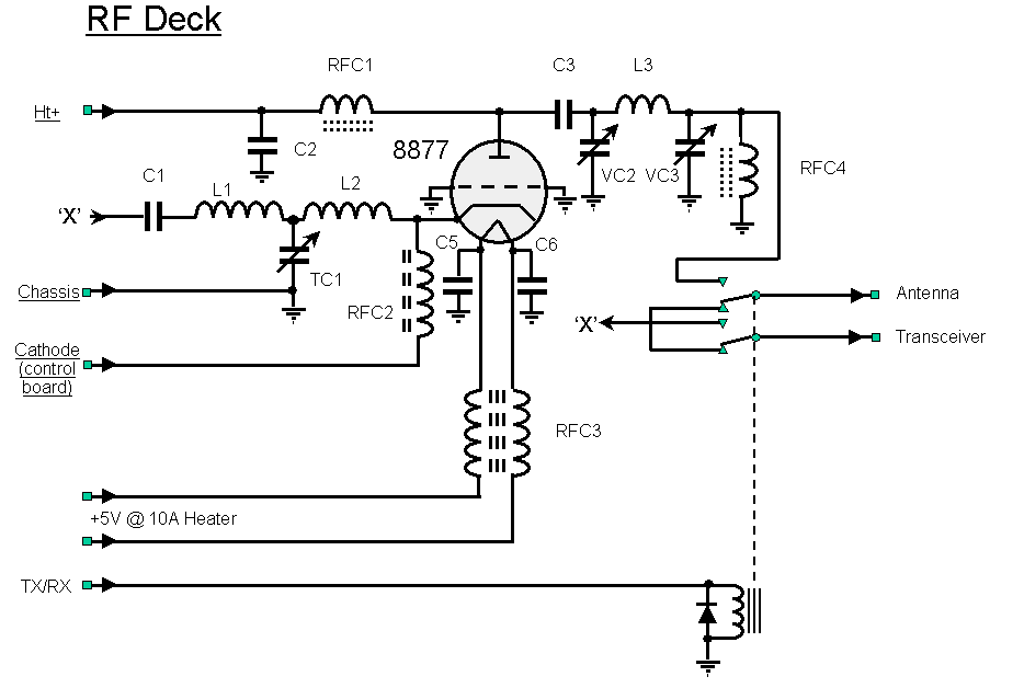
This is the circuit diagram of the RF deck. This is all pretty traditional with little surprise.
Note 1: C2 consists of a feed-through capacitor and a 500pf, 7.5kv button capacitor placed next to the anode
choke.
Note 2: VC3 was very nearly fully engaged when tuned and I couldn't compress the coil, so I added a 7.5kv 1000pf capacitor in parallel.
Click on the component to see a photograph

The DXpedition Amplifier RF Deck
Parts List
| RF Deck | |||||
| Supplier | Part | Number | QTY |
Description |
|
| Cathode side | |||||
| Maplin | RFC3 | LB12N | 1 | 3/8" ferrite rod (for filament choke core) 14-turns, bifilar-wound,16swg insulated, close wound |
|
| College | RFC2 | 1 | 85mm length of 20mm PTFE rod 50-turns 22swg on tufnol or PTFE rod |
||
| TC1 | C804 | 1 | 100pf Jackson panel mounting variable capacitor (input tuning) or equiv. | ||
| L1-L2 | 2 | 10-turns, 18swg, 20mm diameter, spaced 1-turn | |||
| C5-6 | |||||
| RS | C1 | 1 | 4,700pf mica | ||
| Anode side | |||||
| Surplus | VC1 | 1 | 3-30pF vacuum variable (Jennings or Comet) | ||
| Surplus | VC2 | CAV-250F20 | 1 | 250pF, 2kV Johnson variable capacitor or equiv. | |
| College | L3 | 1 | 18" 6mm pure copper tube (do not use car brake pipe) 3-turns, wide spaced, 32mm dia (silvered) |
||
| College | RFC1 | 85mm length of 20mm PTFE rod 50-turns, 22swg, close wound |
|||
| RFC4 | 85mm length of 5mm PTFE rod approx 60-turns 22swg, close wound |
||||
| 1 | Eimac 8877 valve | ||||
| Surplus | (TUA)SK2200 | 1 | Johnson ceramic 8877 base | ||
| Surplus | (TUA)C8877 | 1 | 8877 teflon Chimney | ||
| RadioDan | CX-800N | 1 | Dual N-type coaxial relay | ||
| College | 1 | 12" length 1/2" 18-guage brass strip to connect 8877 anode to anode choke and C3 (silvered) | |||
| RF Parts | C2a | 580500-7 | 1 | 500pf 7.5kV doorknob | |
| Linear Amp UK | C2b | 1 | 750pf feed-through capacitor | ||
| RF Parts | C3 | 1 | 1000pf 20kv doorknob | ||
| RF Parts | HV-20 | 3ft 20swg 30kV HT cable | |||
