The Amplifier Power Supply
Part C - The Control Board
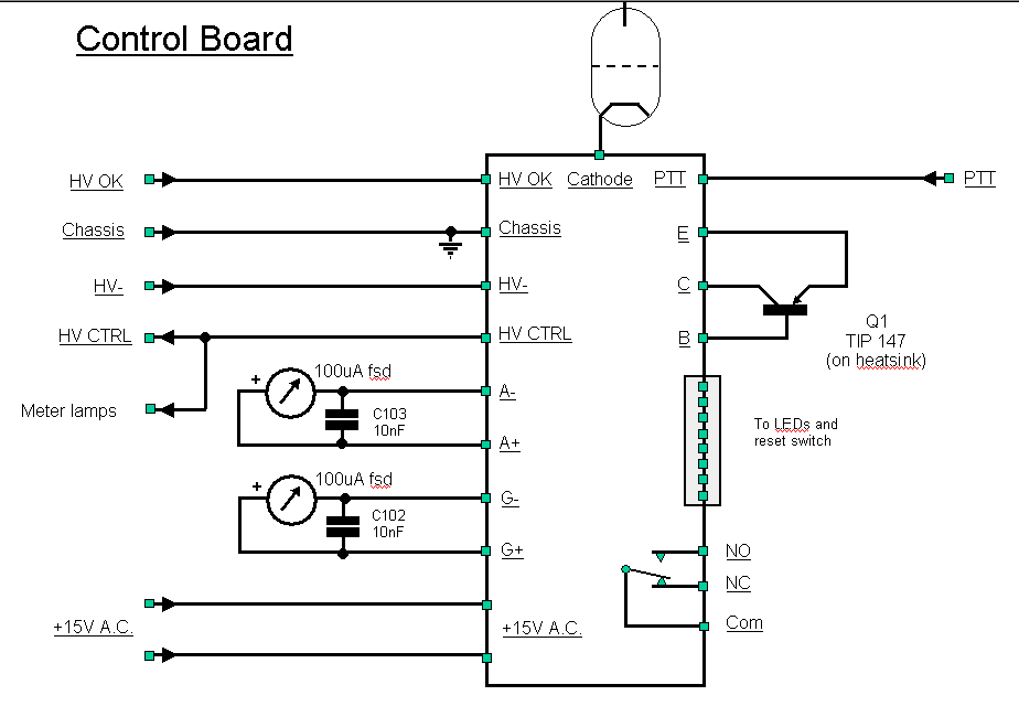
The third power supply circuit diagram shows the control board and associated circuitry. Couple of changes:
-
An extra bit of circuitry (not shown) is the use of the ancillary relay outputs (NO, Com) to switch the +12v antenna change over relay - an 18 ohm 3watt resistor is placed between the relay and the unregulated +19v output on the control board.
-
The +12v, 8cm fan and the four meter lights are driven from the +12v HT CTRL output of the control card - i.e. the fan and the lights come on after the 3-minute delay.
Click on the component to see a photograph

Control Board Circuitry
The key parts of the above circuit are:
-
Grid current and anode current meters
-
Antenna relay switching
Parts List
| Controller board | |||||
| Supplier | Part | Number | QTY |
Description |
|
| Downeast | TRISUP | 1 | Triode Power Supply Control kit | ||
| RS | 336-747 | 1 | Switch, pushbutton, panel mount, N/O, black | ||
| RS | 213-4975 | 2 | LED, indicator, c/w flat top, waterproof, NPB, IP64, fresnel lens, red | ||
| RS | 213-4981 | 1 | LED, indicator, c/w flat top, waterproof, NPB, IP64, fresnel lens, green | ||
| RS | 213-4997 | 1 | LED, indicator, c/w flat top, waterproof, NPB, IP64, fresnel lens, amber | ||
| Farnell | 152-201 |
1 |
Jack socket 3.5Mmm panel mounting (TX / RX lead to transceiver) | ||
| CPC | PM11119 | 2 | Monacor moving coil meter - 100microAmp | ||
| CPC | PM11191 | 4 | Monacor meter back lights | ||
| Overclockers | Papst 8412 | 1 | NGL super quiet fan (PSU section) | ||
| RS | 214-2522 | 1 | 18 ohm 3w resistor, metal oxide film | ||
