Frame Relay Services (FR)
© Mercury Communications Ltd - August 1992
![]() Network Part 5: Where now frame relay in 2007
Network Part 5: Where now frame relay in 2007
![]() 2007
network writings:
2007
network writings:
![]() My
TechnologyInside blog
My
TechnologyInside blog
When it comes to looking at the numerous technologies and services that fall under the banner of 'broad band' confusion seems to be the watchword! N x 64 switched services, frame relay, SDMS (Switched Multi-Megabit Data Service), ATM (asynchronous transfer mode), SDH (synchronous digital hierarchy), and cell relay all seem to be talked about in the same breath. Mix this with acronyms such as MAN (Metropolitan Area Network), WAN (Wide Area Network), and DQDB (Distributed Queue Dual Bus) then it begins to look like that technology has gone mad. The aim of this, and future issues of Technology Watch, is to describe these technologies and/or services and try to understand how they relate to each other. In issue #1, TW looked at SDH and showed that PTOs currently use plesiochronous techniques to multiplex many channels of voice or data over backbone links at rates up to 565Mbit/s. In time, these will be replaced by SDH links that will be able to support all of the data transmission protocols described in this and following issues of Technology Watch.
The Start of It All - X.25
Packet switching has been with us since the early 1980s in the form of the CCITT X.25 packet protocol standard. A packetcombines of a number of bytes (octets) of user data, generally known as a payload, together with a header which contains the destination address and other control information. A packet can be carried over any physical medium such as copper coaxial or twisted-pair cable, fibre-optic or radio. Also, packet protocol is usually independent of the method used to encode the data on the transmission medium and the speed of transmission. For example, X.25 can be carried equally well as a pure packet on a personal computer local area network (LAN), or encoded in PDH or SDH format for transmission via fibre-optic or radio backbone links by a PTO. In Mercury's case, it can also be carried by its bearer Nx64 SwitchBand service.

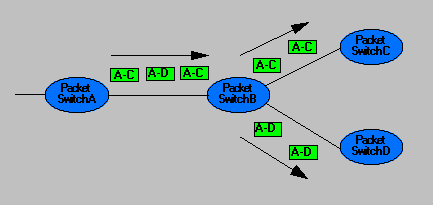
Figure 1 - A Typical X.25 Packet Based Network
The CCITT X.25 standard was refined in the early 1980s when the main medium for packet transmission was coaxial or twisted-pair copper cable. Because of this, the X.25 standard focused to a high degree on reliability and resilience through excellent in-built error correction protocol.
To understand how X.25 error correction works, consider a packet [A-C] in Figure 1 being sent from switch A, via switch B, to the designation switch C. The packet header not only contains the destination address (in this case, switch C) but also a cyclic redundancy code (CRC) error detection byte. A CRC code is a unique signature based on the data held in that packet. When the [A-C] packet is sent from switch A to switch B, a copy is still held by switch A. On arrival at switch B, the same signature algorithm is executed and if the new signature matches the one contained in the received packet, the data is forwarded to switch C and switch A is notified that the packet was correctly received. On the other hand, if an error is detected, switch B raises an automatic request for repetition (ARQ) and sends this back to switch A. The packet is then re-sent until it has been correctly received. As this process takes place on each and every switch in the network, the time overhead of error handling can be seen to be very high. When X.25 was defined it was felt that access speeds of up to 64Kbit/s were adequate for all future needs. This is not now the case.
Another limitation of X.25 is its inadequate support for real-time data transmission such as found with voice or video applications. Voice data must be transmitted through a network with a predictable delay otherwise unacceptable gaps in the data may occur. These are of no concern when transferring files between computers but a pause in a voice or video transmission would be most disconcerting. Gaps, long delays or jitter can occur on a X.25 packet network for two reasons:
Due to the high complexity of the switching nodes necessitated by error correction, they can only operate at low speeds. This means that delays and jitter (variation of delay) will be large.
X.25 packets can be of any length from a few bytes to several megabytes so if long file-transfer packets are mixed with short packets containing voice on a network it is possible that the packets containing the voice data will be subject to excessive and unpredictable delays at peak loading periods .
All of the new wide/broad band services are proposals from various companies and standards bodies that overcome these limitations of X.25 by one method or another, viz.
Feature          X.25     Frame     ATM
                          Relay
Variable Length   Yes       Yes      No
Frame
Error Detection   Yes       Yes      No
Error             Yes        No      No
Correction
To reiterate, X.25 has a variable packet (frame) length making it unsuitable for real-time data transmission. By keeping the length of all frames constant (fixed lengths frames are called cells), ATM can be made to support both real-time and LAN-to-LAN file-transfer applications.
Because fibre optic based transmission is inherently more reliable, the X.25 error correction methodology can be discarded. With new broad band protocols it is up to the application at the far end of the network to tell the originating application that it has not received a packet. However, with frame relay, single bit errors in the header are still detected so that an incorrect destination address can be corrected. If the error greater than a single bit then the complete packet is discarded.
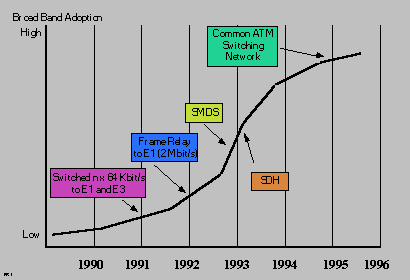
The generic name given to these new protocols is fast packet. This term encompasses all services that accept and forward packets without error correction such as frame relay, SMDS, cell relay and ATM. Figure 2 shows the deployment roadmap of these new services in relation to the Nx64 service.

Figure 2 - Broad Band Technology Adoption Road map
The OSI Model
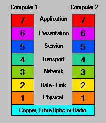
An aid to understanding the various broad band technologies, how they operate, and their differences is through the means of the Open Systems Interconnect (OSI) model. This was developed in 1983 by The International Organisation for Standardisation (ISO) to encourage compatible interconnect between computers. The OSI model partitions the task of computer interconnection into different levels as shown in Figure 3.

Figure 3 - The OSI Model
Interconnection of two computers is via a physical link in the form of copper, fibre-optic or radio. Layer 1 describes the actual electrical and mechanical components in the circuit. Layer 2 describes the circuitry which enables data to be moved. Layer 3 converts a continuous datastream into packets or frames and vice versa. Layer 4 describes how the data is moved to the destination. Level 5controls and monitors the end-to-end connections. Level 6 describes the presentation layer and Level 7 describes the application interface.
The services under consideration here can and do operate at different levels of this hierarchy. For example PDH, SDH and Mercury's SwitchBand service operate at the bottom of the hierarchy at levels 1 and 2, very close to the transmission medium. As X.25, frame relay, SMDS, cell relay and ATM protocols operate at higher levels they can be carried over PDH, SDH, or Mercury's SwitchBand bearer services.
Frame Relay
One way of looking at frame relay is to consider it an as access protocol. It was formalised by ANSI in the T1.S1 standard and is intended for use in public or private networks. Some of the premises on which the specifications were written help speed introduction were:
- A technology was picked that would allow much of the existing equipment to be upgraded by software.
- It still uses the link access protocol for ISDN D channel to allow easy upgrade to LAN bridges and routers. front-end processors and X.25 equipment.
- The committee focused on permanent virtual circuits (PVCs, described later) allowing the benefits of frame relay to be enjoyed while the more complex switching equipment needed to support switched virtual circuits (SVCs) are developed.
- Frame relay was designed to operate over a wide range of interfaces. In a private network, frame relay access can take place over the V series interfaces, fractional E1, basic rate ISDN and primary rate ISDN.
All of the issues that differentiate frame relay have already been touched upon. It is a fast packet, variable frame length, connection oriented data-switching service. Let us look at each of the above characteristics separately.
Fast Packet
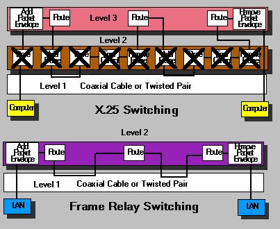
X.25 is limited to a maximum data rate of 64kbit/s. Frame relay access rates start where X.25 leaves off at 64kbit/s and stops for the present at the E1 bearer rate of 2.048Mbit/s. There is no technical reason why frame relay could not provide access at higher rates. For example, in June 1992 Sprint introduced a line of dedicated frame relay switches that offer rates up to 40Mbit/s. These speed increases are achieved by stripping out error correction at Level 2 of the OSI model and moving it to Level 5. Routing is then moved to level 2. This is shown diagramatically in Figure 4.

Figure 4 - Removal of Error Correction in Frame Relay
Variable Frame Length
As with X.25, and in common with Ethernet, frame relay traffic is transmitted using a variable length packet or frame. This means that the source computer determines how much data is inserted into an individual frame. This approach efficiently manages the bursty, unpredictable data traffic associated with computer file transfer. But, it is far from ideal for the transport of stream (or continuous) data such as seen with video and voice as discussed earlier. Thus, frame relay is not suited to video and voice transmission.
Connection Oriented
Frame relay routes through Layer 2 of the OSI model rather than Layer 3 as with X.25. It is able to do this because a frame relay frame affixes only the address of the recipient frame relay device - a router or MUX for example. A good analogy is that frame relay delivers data to the door of the house rather an individual room. Thus a frame relay network has no knowledge of the recipient LAN, of the PC hanging off that LAN, or the application its data is intended for .
PVCs and SVCs
Two types of connection are specified by frame relay, permanent virtual services (PVC) and switched virtual services (SVC). With PVCs, a route through the frame relay network is determined by the network administrator for each node that needs to communicate. These routes are stored in a table and used each time the pair of nodes communicate. With an SVC, as with X.25, a route through the frame relay network is discovered at session establishment and broken down at session termination. If another session is set up it is quite possible a different route could be used. These routes are shared with other packets using other connections. PVC is the easiest to support and initial deployments will be based on this mode.
Congestion Management
Frame relay protocol supports a simple method of managing congestion through the use of two bits in the frame header. These are the Forward Explicit Congestion Notification (FECN) and Backward Congestion Notification (BECN). When a node begins to experience congestion, its sets the FECN bit to a '1' to notify the next node of upcoming congestion. The next node then monitors the FECN bits for a period known as the congestion monitoring period (CMP) and if more than 50% of the packets contain an FECN bit set to '1' the node throttles back the number of packets it generates until the congestion is cleared. Success of this technique eventually depends on the users customer premises equipment (CPE) reducing its rate of packet generation. Vendors and customers agree a committed information rate (CIR) which effectively guarantee the base-level bandwidth available to a customer. This CIR is considerably below the maximum burst rate (BR) of the network.
Applications of Frame Relay
The user requirements that will drive the uptake of frame relay are similar to those found for all wide / broad band services with the exception of video conferencing and voice. These include file transfer, LAN-to-LAN connection, CAD/CAM design interaction, client-server applications, remote RDBMS access, medical and general image processing.
By far the most prominent and interesting, providing as is does near-term business opportunities, is the ever increasing need to pass data between LAN networks more commonly known as LAN-to-LAN interconnect. This generic term is used to cover an extremely wide range of
needs from slow file transfer to transparent interconnect. Here, users need to have similar response times from a remote LAN based PC or workstation as they do from their own local LAN. As LAN-to-LAN communication is seen as such an important subject in the justification of the need to deploy broad band services, it would seem to be worthwhile looking at this in some detail. Therefore a future Technology Watch will be dedicated to this subject.
Horses for Courses
Frame relay sits side-by-side with other broad band services such as inverse multiplexing and Nx64 and positions itself well between slower X.25 public services and other, faster, switched broad band services such as SMDS. As an access protocol, even when ATM eventually arrives in the middle to late part of the decade, frame relay will still be widely used as a means of accessing a fast cell relay service.
In the USA, most regional Bell operating companies are deploying both frame relay and SMDS services and it is clear that they see X.25, frame relay and SMDS as being complimentary with each other. Frame relay has the advantage that it is a relatively simple step beyond X.25. However, SMDS is more compatible within the ultimate ATM / SDH broad band standards and equipment purchased now will still be usable in the ATM regime in the mid to late 1990s. SMDS also provides a connectionless public service which frame relay does not address.
There is plenty of room in the market place for all these access standards but there will be an urgent need for a high level of clarity and understanding in the PTO marketing organisations if customers are not to be confused
