The Challenges
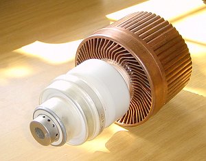 The heavy Russian
GS-35 valve
The heavy Russian
GS-35 valve
Many VHF amplifiers are now based on low-cost Russian valves such as the GS-35 shown in the picture on the right. I've had this one sitting on the shelf for several years now, originally sold to me by Geoff, GJ4ICD. Don't take me wrong, this is a lovely valve but it was definitely not an option for this design. Why? It weighed 2.5kG compared to 0.7kG for the more expensive 8877 / 3CX1500A7 made by Eimac. I doubt that in the UK you could even buy the amount of copper used in the anode cooler for the price I paid for the complete valve! So, an 8877 it had to be.
Another factor that led me to the 8877 is that it is such a superbly linear valve and I have never had any problems with a previous design. Bases are
relatively easy to get hold of and there are many trusted and tried designs to mull over for ideas.
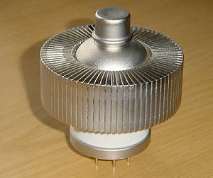 The
Eimac 8877 transmitting valve
The
Eimac 8877 transmitting valve
Following the choice of the valve, I felt the next biggest challenge was not so much the design of the the RF deck or the control electronics, but finding an appropriate HT transformer. That was potentially the heaviest and largest component.
Most of us who have built high-power amplifiers have designed them to be desk bound (or under the desk) so we are not particularly concerned with the
overall size and especially not the overall weight! Indeed, good design practice say that the bigger and heavier the components the better - this especially applies to the HT transformer! I was
going to have a real problem with this and I was sure and it could easily be a project killer.
The transformer decision
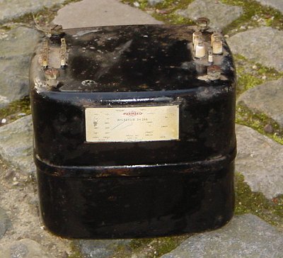 The Parmeko transformer given to me by David, G3FPQ
The picture on the left is typical of the style of transformer most us have used for our amplifier designs. This particular one, sitting in my garage for a couple of years, was given to me by David, G3FPQ when he was having a garage clearout. It is a lovely transformer that has a 2,900 volt secondary, however, it does have one problem - yes, you know what that is - it weighed in at over 30 kG! As they say "no way, Jos�" could I use this in my DXpedition amplifier. Can you imagine me humping this through a departure lounge and putting it on a weighing scale!
And so ensued a few weeks of calling around trying to find whether I could buy a transformer or get one designed that would suit my needs. In my previous 8877 amplifier, based on the design by Geoff, GJ4ICD, I used a 2kVA toroidal transformer bought from Peter Rodmell, of Linear Amp UK who is quite happy to sell hard-to-find amplifier bits and pieces. But, again this was far too heavy and had an inappropriate shape factor for use in this design. I was beginning to despair.
The solution was staring me in my face (as it usually does). I should talk to the same guy who built the transformer for K5AND's 9G amplifier in the US. This turned out to be an excellent decision. Ed, of Heritage Transformers in Kentucky specialises in designing and building transformers and after I phoned him with my specification he provided me several options based on on different cores - perfect!
The nearest design I could have bought off-the-shelf was from Peter W. Dahl & Co. This was a designed for Alpha A77 ETO PA-77 linear amplifier which provided 0-1800-2800 VAC @ 0.7A and +5v @ 10A for the heater supply and it only weighed 23lbs. Not bad I thought! But, Ed's design was better.
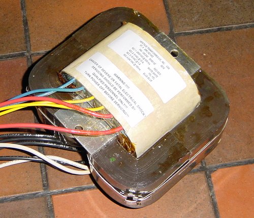 The Heritage Transformer design
Ed came up with a very compact open-core design with a similar specification that only weighted 18lbs and had the following requested secondaries:
-
2,800v @ 700mA
-
240v @ 100mA
I wanted the 240v secondary to power the blower. Because of the open style of the design, I could mount the transformer in a horizontal orientation and place the lower half of the winding through a square hole in the chassis. This would enable me to keep the overall height of the case down to less that 165mm, the maximum I could have if the case was to fit inside pilot's case I had already bought. Perfect! A little discussion finalised the mounting option as shown in the photo above. As I wanted to mount the transformer as close to the side and front panel as possible I did not want the mounting bracket to extend beyond the sides of the core. Ed came up with the perfect solution.
I had decided by this time that the amplifier needed to be able to be run from either a 120v or 240v A.C. mains (power) supply so I decided to run the 240v blower from a secondary winding on the transformer. Ed also designed me a very nice little chassis mounted transformer that provided the 5v and 15v for the heater and control board. This could be mounted in the 8877 cathode section of the case.
How were all the bits going to fit together? I needed to put some careful thought into this which led me to getting out a pair of scissors!